The Linear Motion 120 with HyperX
Linear Motion 120 with HyperX
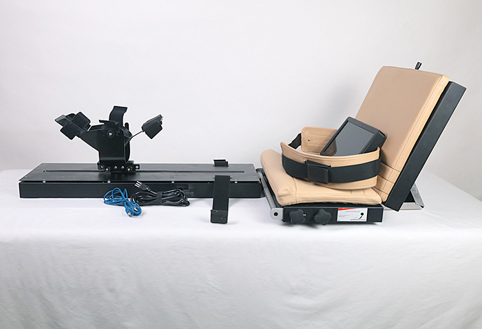
The LM 120 with HyperX is an FDA Class I Medical Device used as a physical rehabilitation apparatus following total knee replacement (TKR) surgery and to rehabilitate sprained or torn ligaments. The LM 120 with HyperX is intended to increase the degree of flexion (bending) and extension (straightening) of the surgically affected limb. The apparatus consists of four main components: 1) the Resting Platform; 2) a Connecting Mechanism; 3) the Actuator Enclosure Assembly; and 4) the Tablet.
Support Platform
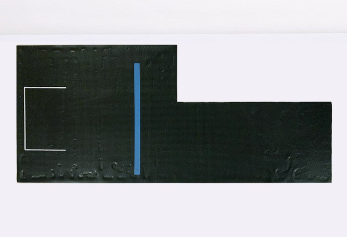
A sturdy base layer of plexiglass covered in non-slip neoprene supports the unit components when placed on a table or bed. The long arm of the L-shaped platform is flipped over to correspond with the right or left positioning of the Actuator Enclosure Assembly and the effected leg. The white outline is positioned close to the wall or head of the bed and designates the positioning of the Resting Platform. The aluminum rectangle of the Actuator Enclosure Assembly rests on the blue line.
Resting Platform
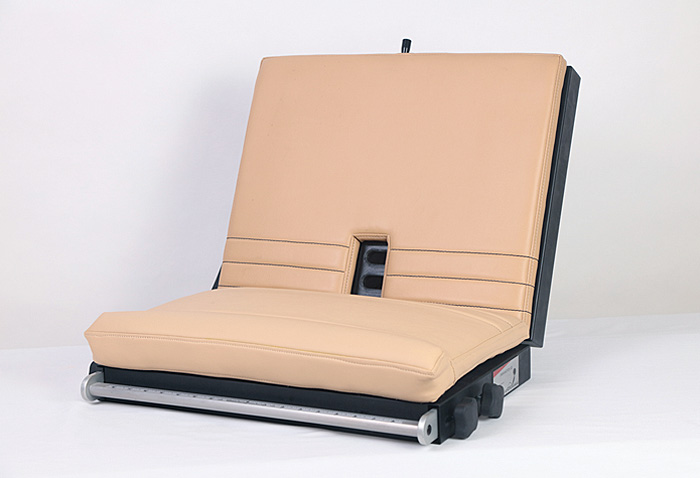
The function of the Resting Platform is to provide a comfortable surface where the client’s hips are stabilized, preventing the hip from rising up, sliding forward or moving side-to-side during therapy of the knee. A one-inch pummel (bolster) at the front of the cushion further restricts client forward movement. The Resting Platform is a two-piece, hinged aluminum frame. The seat is upholstered in high-density foam and medical-grade vinyl, which is impervious to disinfecting solutions.
Resting Platform Belt Positioning Block
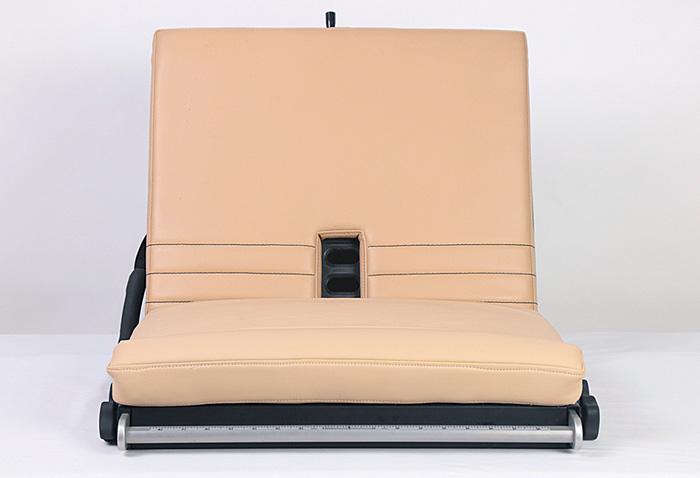
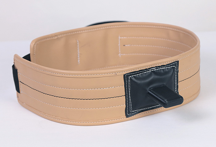
The 3-D printed Resting Platform Belt Positioning Block, with its three slots, is embedded into the backrest of the Resting Platform and serves to anchor the Hip Stabilizer Belt. The client sits erect on the Resting Platform cushion and slides back until his/her buttocks are against the backrest.
Resting Platform Adjustment Bar Rulers
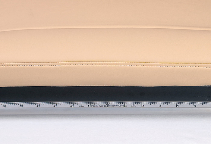
Situated at the front of the Resting Platform is the aluminum square rail of the Resting Platform Adjustment Bar. Mounted on the upper surface of the Adjustment Bar are the Alignment Guides (right and left), metalized rulers marked in inches to facilitate client seating position at 4.5 inches.
Resting Platform Back: Crank and Hinge
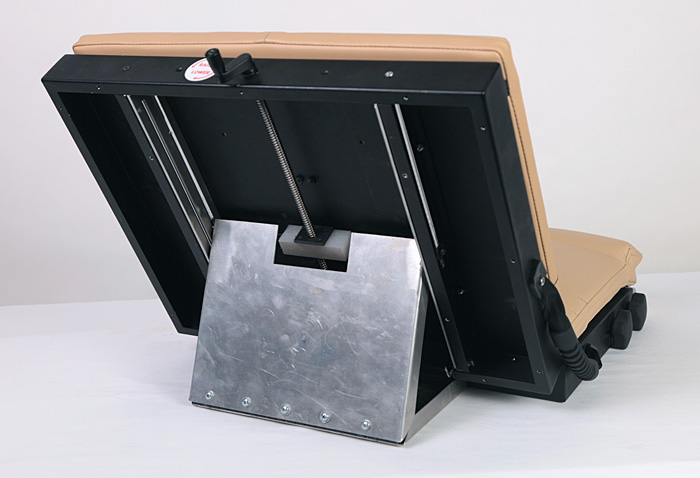
The crank, located at the upper edge of the Resting Platform, is turned clockwise to lower the backrest or counterclockwise to raise the back until the client is comfortable (approximately 65°). Adjusting the crank opens or closes the aluminum, rectangular Resting Platform Back Hinge. This sturdy mechanism ensures client safety and unit stability up to 250 pounds.
Hip Stabilizer Belt
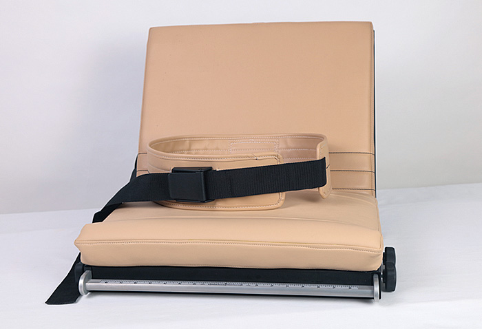
This view shows the Hip Stabilizer Belt, an ample 25-inch long strap attached to a 4-inch wide medical-grade vinyl belt. The strap is threaded through a quick-release plastic cam buckle and locked to encircle the client’s waist. The quick-release cam buckle is a safety feature if the client must exit the unit in an emergency.
Unconnected Actuator and Resting Platform
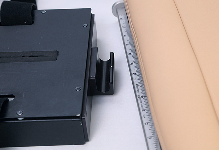
The components of the Connecting Mechanism are depicted individually, unconnected. The Resting Platform Adjustment Bar connects the Resting Platform to the Actuator Enclosure Assembly. Screwed to the front of the Actuator Enclosure box is the U-shaped Actuator Receiver Bar Bracket. A divot (white dot) on the Bracket is lined up with the 4.5 inch mark on either the right or left metal ruler on the Adjustment Bar.
Connected Actuator and Resting Platform
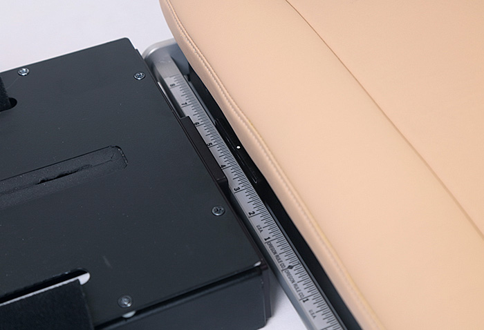
The components of the Connecting Mechanism are connected. During unit set-up, the Actuator Enclosure Assembly was positioned to the right or left of the Resting Platform, depending on which leg is affected. Coupling occurs by lifting and lowering the Resting Platform into the U-shaped slot of the Actuator Bracket. The Resting Platform Adjustment Bar is moved back and forth until the divot on the Bracket lines up to the 4.5 inch ruler mark.
Actuator Enclosure Assembly
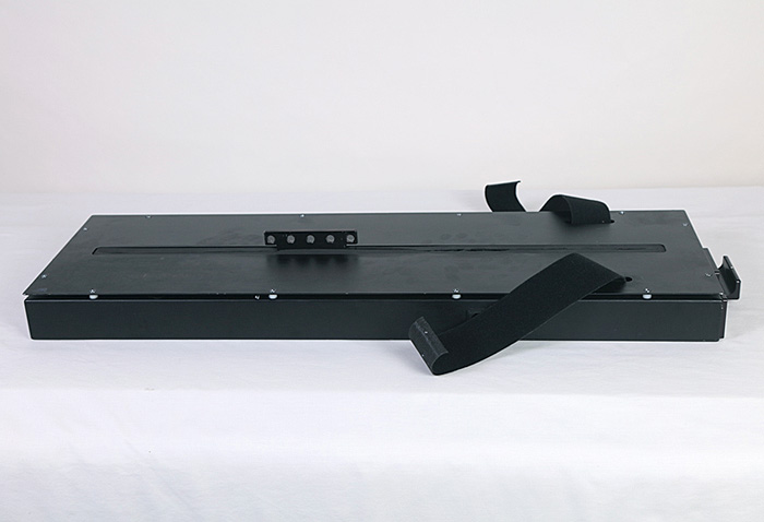
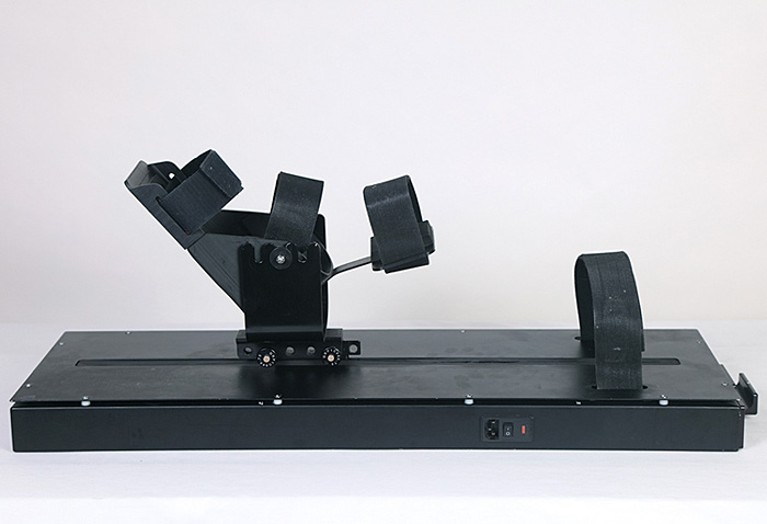
The Actuator Enclosure Assembly, an aluminum box with cover, combines the mechanisms that move the knee through its range of motion. Located at the front of the Actuator Enclosure box is the Actuator Receiver Bar Bracket; located at the back of the Box is the power cord, the Ethernet connector and the lighted on-off switch. Other components include the lead-screw actuator and motor, the Foot Pedal Gantry, the electronics and the HyperX function. The HyperX function is comprised of two hook-and-loop (Velcro) straps screwed internally to a plate on the Box base, with two cams and two forward/reversing motors. The ends of the Velcro straps exit through slots onto the surface of the Actuator Enclosure cover and are laced over the client’s thigh to facilitate extension.
Cradle Assembly
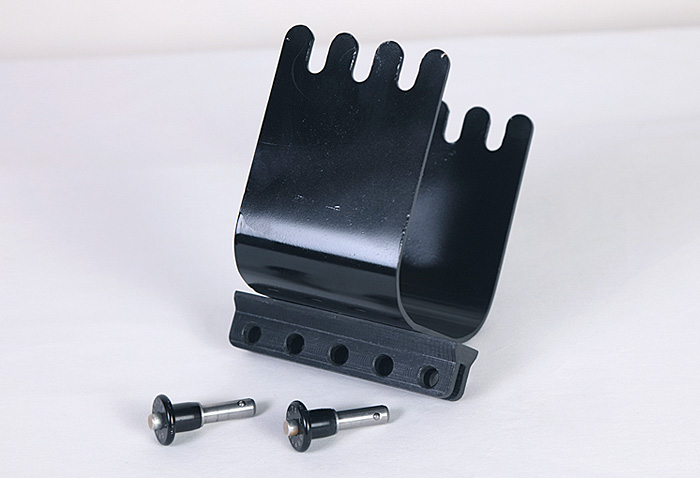
The Foot Pedal Gantry (not seen) is a square aluminum block. It rides back and forth on the lead screw, moving within the center slot opening of the Actuator Enclosure cover. Attached to the Gantry is the Cradle Mounting Bracket. Separately, the four-notched Cradle is attached to the steel Mounting Bracket with its five holes, a configuration designed to accommodate leg lengths greater than 38 inches. These two parts are then placed over the projecting Cradle Mounting Bracket and secured with two, push-button, quick-release pins inserted in holes 2 and 4. Hole 5 is closest to the Bracket (right side of photo).
Foot Pedal Assembly
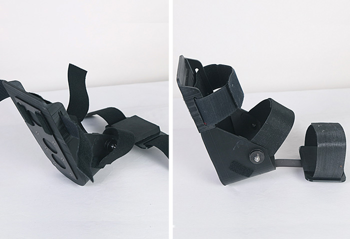
The Foot Pedal Assembly is made up of a Sole Plate, with the aluminum Foot Pedal Brace attached to its underside. A reinforced Heel Cup, attached to the Sole Plate, protects the ankle. Attached to, and extending from, the Heel Cup is the aluminum Foot Pedal Heel Brace, with its slots and straps to secure the lower calf. Velcro straps secure the forefoot, the ankle and the lower calf. A self-clinching stud, washer and bushing combine to form a knob on both sides of the Heel Cup.
Foot Pedal in Place
The Foot Pedal Assembly (the boot) is placed into the middle slot of the attached Cradle, suspended by the knobs on the Heel Cup. This design is engineered to replicate the natural movement of the ankle, pivoting around a fulcrum. As a safety feature, the Foot Pedal Assembly can be lifted free from the Cradle in a single motion.
Tablet
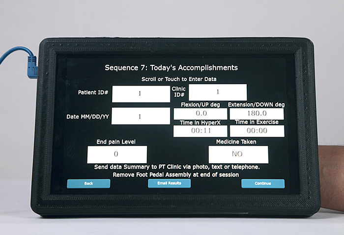
A 10.1 inch hand-held Tablet is wired to the unit to provide power to the Tablet and to communicate with the actuator and motors. Electronics, housed within the Actuator Enclosure Assembly, consist of a custom control board made up of a control processor, motor control and an interface board. Software can transmit the client’s achievements to the orthopedic surgeon and/or the physical therapy clinic.

